Hardware Installation Guide
Introduction
Completing this installation will require these tasks:
- Securing a device under the dash of the vehicle
- Running wires behind molding and airbag emplacements
- Crimping connectors onto the ends of wires
Prior to installation, ensure that you have the following:
- CalAmp LMU-3240 device
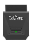
- OBDII extension cable
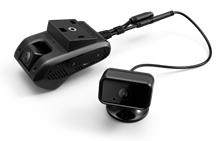
- iOn Vision camera kit:
• Forward-facing camera
• Mounting base
• Rear-facing camera
• SOS button
• Camera power/data cable
- Male and female spade connectors (to connect the camera power/data cable to the OBDII extension cable)
- Car panel dash removal tools (to aid in tucking cables between the windshield and dash)
- Wire ties (to secure devices and cables)
- Double-sided tape (to secure the LMU-3240 in place)
- Alcohol wipes (to clean surfaces prior to adhesive mounting of parts)
LMU-3240 Installation
iOn Vision requires secure mounting in the front of the vehicle to a solid base such as a subdash (not a wire harness) to ensure the correct functionality of the device.
The LMU-3240 should be mounted with the connector down or to the side, and not obstructed by metal above. Make sure that you have adequate space to route the extension cable from the device's final mounting location to the OBDII port under the dash. Avoid mounting the device fewer than 2” from a radio as it can interfere with reception when transmitting data.
Prior to beginning installation, write down the device ESN from the label and keep it handy. You'll need this during the calibration portion of the installation.
-
Connect the female end of the extension cable to the LMU-3240, leaving the male end of the cable unplugged from the OBDII port.
-
Remove the lower panel of the dash to select a suitable mounting location and install the device. (The device must be securely attached to a rigid structure with double-sided tape and cable ties.)
IMPORTANT: Do not place adhesive over the ESN, as you may need to refer to it later.
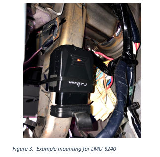
- Turn on the engine, and with the engine running, plug the male end of the cable into the OBDII port and cable tie connector.
NOTE: If the unit is plugged in while the vehicle is off, it will need to complete the detection process on the next ignition on cycle to operate correctly.
Camera Installation
Forward-Facing
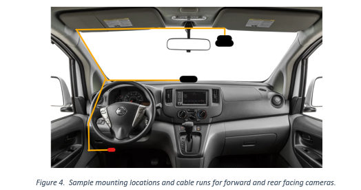
- Select a proper installation position. (The recommended position is high on the windshield, to the right of the rear-view mirror.)
NOTE: See the bulleted list in the "Calibration (Installer App)" section (under "Camera Info Screen") for tips on proper placement for the camera.
-
Clean the area using an alcohol wipe and allow it to dry before proceeding.
-
Tear the protective film off the 3M sticker on the mounting base and then attach the mounting base to the windshield. Press the mounting base tightly to the glass to ensure that the contact surface is flat.
Wait for 1 hour before you proceed to the next step.
-
Connect the forward-facing camera to the mounting base.
-
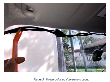
Remove the existing connectors on the red, yellow, and black connectors on the camera power/data cable. Crimp a male spade connector on the black (ground) wire. Crimp both the yellow and red wires into one male spade connector. Connect the camera power/data cable to the forward-facing camera. Tuck the cable under the headliner toward the driver's side of the vehicle.
-
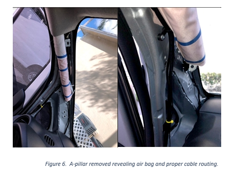
Remove the A-pillar panel (recommended) to identify if the vehicle is equipped with an airbag. If it is, make sure that the wires are routed behind the airbag so that they don't block it if it's deployed.
-
Route the cables down the A-pillar toward the OBDII port; this will reduce the amount of cable you will have to hide. Tuck the cable between the dash and lower windshield using a panel trim removal tool.
Rear-Facing
-
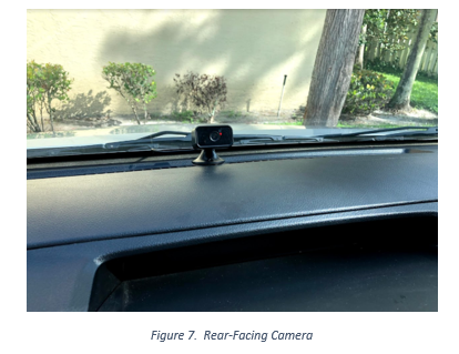
Select an installation point for the rear-facing camera, preferably in the center of the dash close to the lower windshield.
-
Clean the area with an alcohol wipe and allow it to dry before proceeding.
-
Remove the protective film from the 3M sticker on the base of the rear-facing camera. Press the base of the camera to the dash, applying pressure to ensure that the mounting is secured in place.
-
Route the rear-facing camera cable along the A-pillar to the point where it can connect to the male connector on the camera power/data cable.
- Complete the installation by making sure that all wires are securely fastened and the panels are all replaced securely.
Calibration (Installer App)
You can install the camera system without the Installer Companion app, but if you do use it, you can confirm that the network connection and camera orientation are correct.
The Installer Companion is a helper Android application used by an installer or a fleet manager. It communicates with the iOn Vision app on the camera with a Wi-Fi Direct connection.
Minimum Supported Android Version: 5.0 Lollipop (SDK version 21)
Welcome Screen
Camera Screen
-
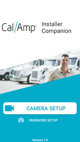
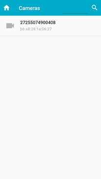
On the Welcome screen, select Camera Setup to launch the Cameras screen.
-
Select the iOn Vision camera that is within Wi-Fi Direct range of your Android device.
Connect to Camera Screen
After you select a camera, the Connect to Camera screen will appear, on which the app will initially create a connection from the Android device to the iOn Vision camera.
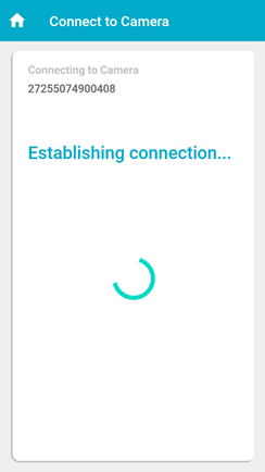
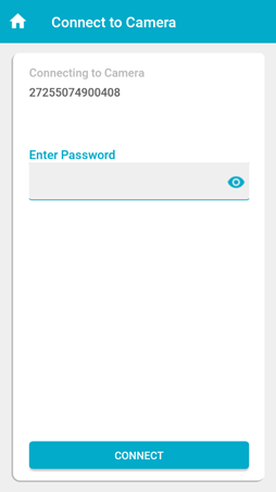
After a connection is established, the password prompt will be displayed.
- Enter your password to access the camera. (This password will have been provided by the fleet manager.)
Camera Info Screen
After authentication is complete, you will be allowed to view a live camera feed. The feed will show a picture-in-picture view of the road-facing and driver-facing cameras.
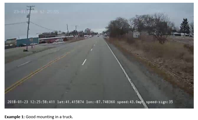
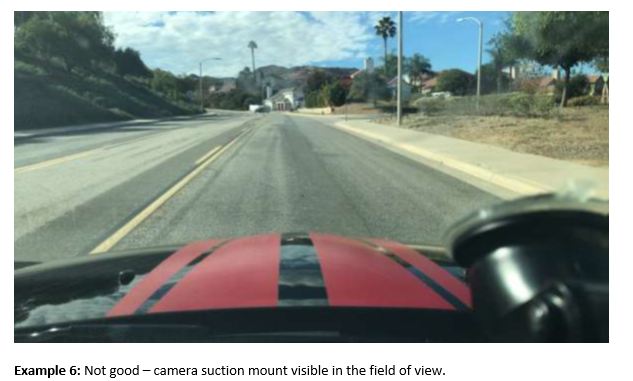
The camera installation should follow these general principles:
- Ideal location: Center. If a center mount is not possible, the closer to the center, the better.
- Ideal height: Highest point, behind the rear-view mirror — as high as possible.
- Field of view: The view should be clear of any occlusions (such as an E‑ZPass tag or the rear-view mirror).
- Negative pitch angle: The camera should have a negative pitch angle, which means that it should "look down" by a few degrees. This ensures that the field of view does not have too much sky.
- Limited view of the vehicle hood: Ideally, mount the camera so that a minimal amount of the vehicle hood is visible.
- Wiper blades: If possible, place the camera in an area swept by the wipers.
NOTE: You must also comply with local regulations on camera mounting on windshields.
Mounting Examples
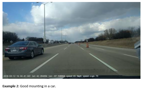
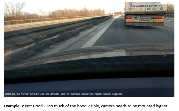
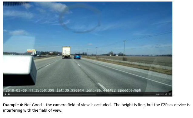
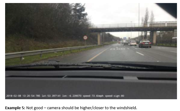
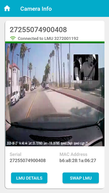
At the bottom of the Camera Info screen, you'll see these options:
- LMU Details: Enables you to view current information about the LMU that is paired to the camera.
- Swap LMU: Enables you to assign a specific LMU to the camera.
- At this point, you should verify that the ESN displayed on the screen matches the one you recorded at the beginning of the installation process.
Available LMUs Screen
- If it doesn't match, tap Swap LMU to launch the Available LMUs screen.
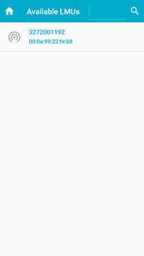
- Select the correct LMU in this list to explicitly pair it with the camera to which you are currently authenticated.
NOTE: The currently paired LMU to the camera will be highlighted with blue text. All other LMUs in proximity will be highlighted with black text.
- If the camera feed is lost after pairing the camera with a different LMU, select Home and go through the process to reconnect with the camera.
LMU Details Screen
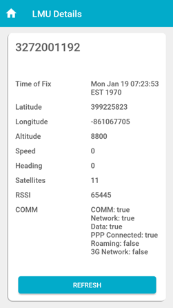
If you tap LMU Details on the Camera Info screen, the following screen will appear and display the network and GPS statistics from the LMU.
Updated over 3 years ago
